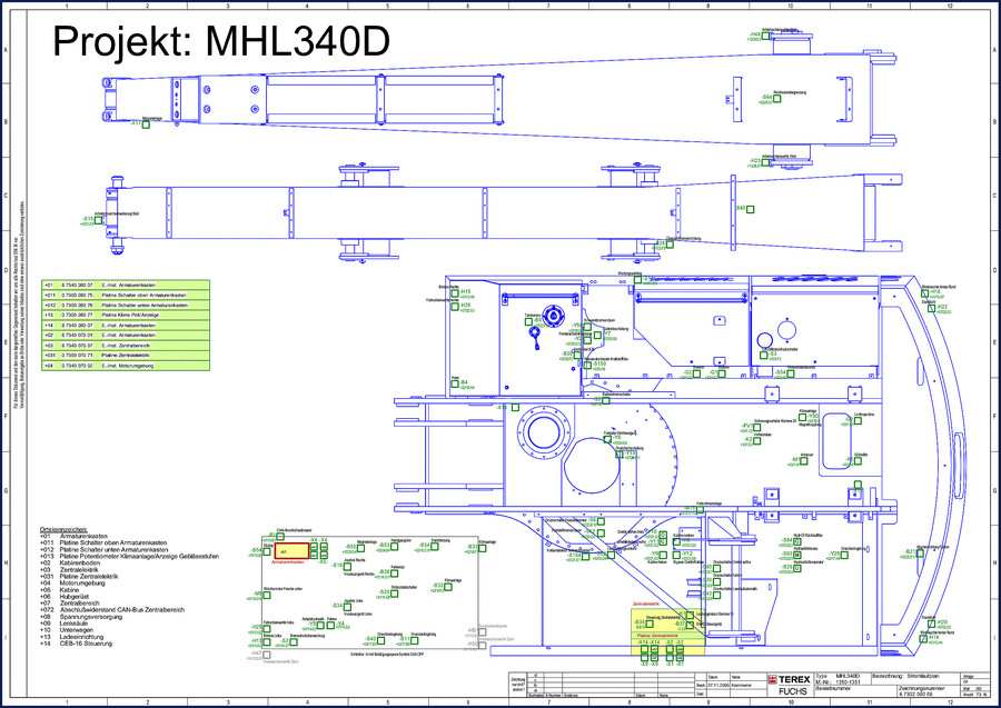
Terex Fuchs MHL340D Wiring Diagram – 73-Page OEM Factory Manual
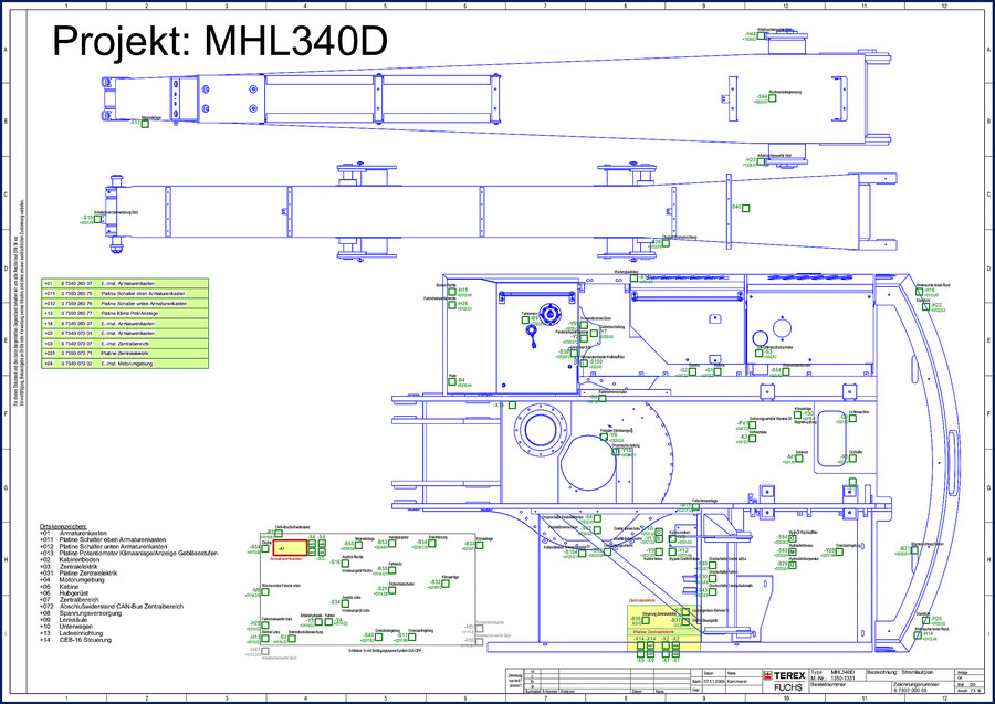
If you’ve ever had a MHL340D come in with a dead display, a joystick that doesn’t respond, or a hydraulic function that only works when it feels like it, you know the drill. You start pulling panels, scanning for burnt wires, checking fuses, and before long you’re staring at a nest of Deutsch connectors and thinking, “I wish I had a map.” That’s what this is. 73 pages of the factory wiring diagram, direct from Terex Fuchs. No aftermarket translation, no redrawn schematics that drop a pin or miss a splice. This is the original German engineering document, the same one the factory techs use. And it’s built for real work.
73 Pages of Factory Wiring Data
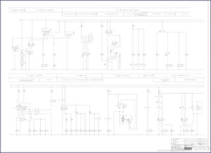
73 pages covers every electrical corner of the machine. The diagram breaks down by location zones: armature cabinet (+01), cab floor (+02), central electrics (+03), motor area (+04), cab (+05), superstructure (+06), central area (+07), voltage supply (+08), steering column (+09), undercarriage (+10), loading equipment (+13), and the CEB-16 controller (+14). Each page gives you the exact grid coordinates (e.g., +07/20.F8) so you can trace a wire from the joystick all the way to the solenoid. You need the charge pressure switch? Look at the breakout for +07/23.E8. That’s the kind of precision that saves you a digital multimeter session that runs into overtime.
What the OCR Tells You: Component Locations
Pull up page 1 of the PDF and you’ll see the raw component list straight from the factory. Items like “Blinken Rechts -H15 +01/13.H6” – that’s the right turn signal relay, located in the armature cabinet at grid H6 on drawing 13. Or “Fahrscheinwerfer rechts -H26 +07/22.G1” – right headlight, central area. Every component has a functional identifier (e.g., -B9 for tank sensor, -Y59 for swing brake release, -B38 for seat heater). The OCR excerpt is dense, but once you know the pattern, it’s like reading a parts catalog. You don’t need to flip through 200 pages of theory. This is a working document.
How to Use This Diagram on the Bench
Lay the PDF open on a tablet or print the relevant pages. Start with the zone that matches the symptom. For a non-cranking engine, go to the starting circuit section (+04 motor area). Identify the battery master switch -G6 (+01/12), the starter relay, and the safety interlocks. Then cross-reference the pin numbers on the CEB-16 controller (+14). The manual uses standard German abbreviations (e.g., “E.-Inst.” for electrical installation, “Platine” for circuit board). If you’re not fluent in German, keep a translation list handy – but the numbers and coordinates are universal. A good tip: mark the page with the CAN bus termination resistors -R1 (+01/15.B3) – that’s a common failure point that causes intermittent communication errors.
Does This Manual Cover the Fuel System?
No. This is a Wiring Diagram only – it covers the electrical and electronic systems, including the engine control unit (ECU), sensors, actuators, lighting, hydraulic control solenoids, and the CAN bus network. The fuel system’s electrical components (like the water separator sensor -S150 at +03/3.H8) are included, but mechanical fuel system specs are not. If you need fuel pump pressure or injection timing, you need the service manual. For electrical troubleshooting, this is the document.
Audience Fit: Who Needs This
If you own a MHL340D and do your own electrical repairs, you are the target audience. The same goes for fleet mechanics who maintain multiple Terex Fuchs machines. The wiring diagram is also useful for technicians who retrofit attachments (e.g., grapples, magnets) because the factory harness layout shows where you can tap into the control circuits. Beginners should be aware: this is a professional-level document. It assumes you know how to read a schematic, how to use a multimeter, and how to safely disable high-voltage circuits. The machine operates on 24V DC, but some components (like the alternator) can produce dangerous currents. Disconnect the battery and wait 5 minutes for the capacitors to drain before probing.
Source Validity: OEM vs. Aftermarket
I have seen aftermarket wiring diagrams for the MHL340D that were traced from a machine that had already been modified. They showed wires that didn’t exist and missed pins that were critical. This PDF is a direct scan of the original Terex Fuchs document. The file name itself – TEREXFUCHS_MHL340D_Wiring_Diagram_de-46111007828.pdf – indicates it’s a German-language factory release. The part numbers and location codes match the ones stamped on the actual harnesses. If you’re serious about not cooking a $2,000 controller, you use the OEM source. The Automotive Wiring standards are the same, but this is specific to the machine. Compare it to the Automotive Wiring general principles, and you’ll see the difference in detail.
Related Manuals for Other Models
- TEREX FUCHS MHL340D Wiring Diagram – same machine, the document you’re looking at
- TEREX FUCHS MHL380D Wiring Diagram – for the larger MHL380D, shares many electrical components
- Terex Fuchs MHL360D Wiring Diagram – mid-range model, useful for cross-referencing
- How many pages does the MHL340D wiring diagram have?
- 73 pages.
- What if I need a wiring diagram for a different Terex Fuchs model?
- The MHL380D and MHL360D share about 70% of the electrical architecture, but the pin assignments and optional equipment differ. For a specific model, you need the exact factory diagram. Mixing diagrams can lead to incorrect connections – especially on the CAN bus terminations and the CEB-16 controller. The connectors are physically the same, but the wire colors and pin functions vary. Always use the model-specific document. We stock both the MHL380D and MHL360D wiring diagrams, linked above.
If you’re ready to stop chasing ghosts in your MHL340D’s electrical system, TEREX FUCHS MHL340D Wiring Diagram is the move. Download the Factory Manual and get back to work.
Reviews
There are no reviews yet.