If you’ve ever chased a short on a 950H and ended up cross-referencing three different aftermarket diagrams that don’t match the harness you’re staring at, you know why this 20-page OEM Caterpillar 950H, 962H, IT62H 2011 Electrical Schematic exists. Caterpillar didn’t print these for show. They printed them so a tech can put a meter on the right pin the first time. This is the factory paper – the same one their own field service guys use when a loader drops dead in the pit. It covers the 950H, 962H, and the IT62H Integrated Toolcarrier, all 2011 model year.
950H, 962H, IT62H Electrical Schematic: Factory Wire Data
Look at the Table of Contents. You get Component Location split into Volume 1 – Chassis and Volume 2 – Cab. Connector Location, same split. CID/MID/FMI diagnostic codes – all factory-defined so you can pull the actual code from the ECM and cross it to a wire and a component, not some generic list. The Wire Description section runs two pages per volume. That’s where you find gauge, color, and circuit function. No guessing.
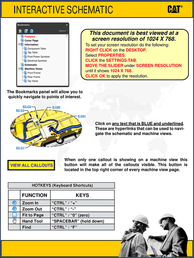
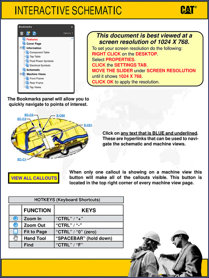
This schematic is interactive. The PDF includes bookmarks and hyperlinks – click any blue text in the schematics and it jumps you to the machine view or the component location. Hotkeys are listed: CTRL+ for zoom, CTRL- for zoom out, SPACEBAR for hand tool. Set your screen resolution to 1024×768 for best viewing, as noted on page 1 of the manual.
What CID/MID/FMI Codes Are Included?
Volume 1 – Chassis and Volume 2 – Cab each have a CID/MID/FMI section spread across two pages. That covers the full list of diagnostic codes for the engine, transmission, hydraulic, and cab systems. If the ECM spits a code like CID 0041 – you can look up exactly what sensor or actuator it refers to, and the FMI tells you if it’s a voltage high, current low, or mechanical fault. The 962H and IT62H share most of the same electronics architecture, but the code tables are specific to the machine serial numbers listed: for 962H, N4A1257-2059, M3G542-UP, MAL1-UP, K6K435-UP; for IT62H, M5G476-478; for 950H, N1A3213-4214, JAD188-UP, M1G1783-UP, K5K435-UP. If your machine falls outside those, check the serial number coverage on the cover page.
Two Volumes of Component Locations
Volume 1 covers the chassis: alternator, sensors for rail pressure, rear axle oil temp, rotary lift and tilt position, transmission input/output speed, and every solenoid you can think of – A/C clutch, auxiliary third function, axle cooler clutch, dump anti-drift, raise prop, ride control, even the ether aid. Volume 2 covers the cab: HVAC controls, dash switches, ECM connectors. Each component is mapped to a schematic location and a machine location. The Machine Views section shows harness connector and component locations with callouts. Click “VIEW ALL CALLOUTS” to see everything at once. This is the kind of detail that saves you from pulling a dash apart to find a relay that lives under the cab floor.
Check the Wire Description Before You Solder
Wire Description in Volume 1 (Chassis) runs page 1 of 2 and page 2 of 2. Same for Volume 2 (Cab). Each entry lists the wire number, gauge, color, and the circuit it belongs to. If you’re adding an aftermarket accessory like a work light or a beacon, you need to tap into the correct circuit without overloading the factory fuse. The schematic gives you the exact wire to splice – or better, tells you which connector pin to use. Don’t trust aftermarket pinouts; I’ve seen three different sources give three different wire colors for the alternator excite circuit on a 950H. Use the factory document.
Interactive Schematic: How It Works
The PDF opens with a navigation panel. You can jump directly to any section using the bookmarks. The schematic pages themselves have hyperlinked component labels – click on “EC-C2” and it takes you to the machine view where that connector lives. The hotkeys make zooming and panning fast. This matters when you’re trying to trace a harness that weaves through the frame and you need to see both ends of a wire on the same screen. For more on reading modern wiring diagrams, check Automotive Industry Overview – but for actual work, stick with the OEM schematic.
Need more supporting documents? The Caterpillar 950H 2005 Parts Catalog is a good companion for locating physical parts. If you’re troubleshooting hydraulics along with the electrical, the Caterpillar 950H 962H IT62H 2010 Hydraulic System manual covers the valve body and pump circuits. And of course, the Caterpillar 950H, 962H, IT62H 2011 Electrical Schematic – 20 Page OEM Manual is what you’re looking at now – make sure you have the right one for your machine serial number. For general background on automotive wiring principles, that’s fine, but nothing replaces a factory schematic when the loader won’t crank.
- Does this manual cover the fuel system?
- No. This is an Electrical Schematic only – fuel system diagrams are not included. You need the corresponding service manual for fuel routing and injection timing.
- Can I use this for a 950G?
- No. The G-series uses older multiplexing and a different cab harness. The 2011 H-series is a separate platform with different connector layouts and CID/MID/FMI codes.
- What wire gauge information is provided?
- Each wire in the Wire Description tables lists the gauge (e.g., 14 AWG, 16 AWG), color code, and circuit function – covers both chassis and cab volumes.
- Is the schematic interactive?
- Yes. The PDF has hyperlinked components, bookmarks for each section, and hotkey navigation. Click any blue underlined text to jump to machine views.
You’ve got the loader in the bay, the dash lights are blinking, and you need the real wire colors, connector pinouts, and diagnostic codes. Download the Factory Manual and stop guessing. A 20-page OEM schematic is cheaper than a fried ECM from a miswired jump start.




Reviews
There are no reviews yet.