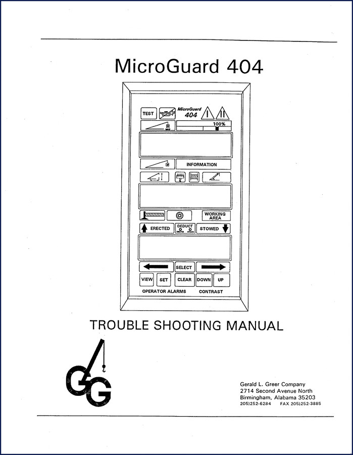
Greer 404 Troubleshooting Manual – OEM Factory Specs for MicroGuard 404
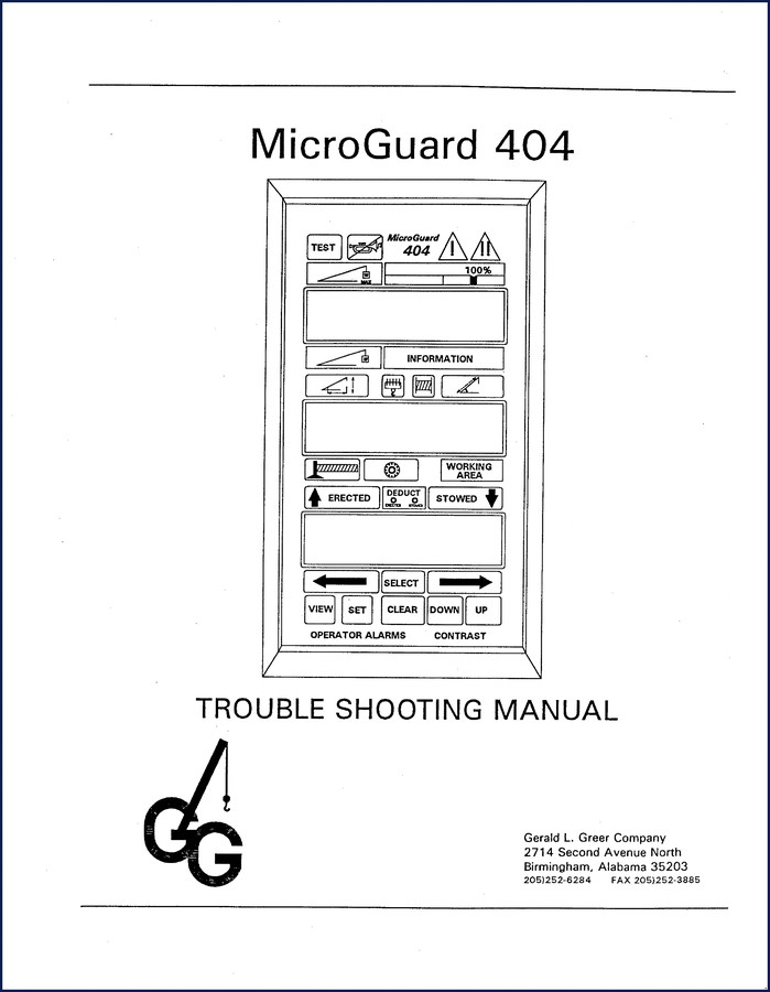
I’ve been twisting wrenches in San Antonio for 28 years. Seen too many guys spend a whole shift chasing a phantom fault on a crane because they didn’t have the right documentation. This Greer 404 Troubleshooting Manual is what you get when you want to stop guessing and start fixing. It’s 39 pages of everything from pressure transducer checks to board replacement. No reprints. No aftermarket junk. This is the OEM book from Gerald L. Greer Company out of Birmingham, AL.
System Faults: From Pressure Transducers to Display Unit
The manual doesn’t waste time. Page 4 drops you straight into Pressure Transducers AIN 0 and AIN 1. You’ll find Boom Extension AIN 2 on page 6, Boom Angle AIN 3 on page 8, and Super Structure Angle AIN 4 on page 10. Each fault is laid out with specific symptoms and the exact test points to hit. Then you hit page 14 – that’s where the ROM and RAM faults live: Executive ROM, Personality ROM, Scratchpad RAM, Duty ROM, Current Duty Bad, Configuration Uncalibrated, Digital I/O and Analog I/O, and Display Unit. One page covers all those. No fluff.
Do You Know the Difference Between Executive ROM and Personality ROM?
If you’re swapping boards without checking those chips, you’re wasting time. The manual walks you through each ROM replacement separately – Executive on page 28, Personality on page 28, Duty on page 29. And they give you General Chip Replacement Information on page 34. I’ve seen guys pull the wrong ROM because they didn’t read the labels. This manual labels everything. Use it.
39 Pages of Factory-Approved Diagnostics
The full index covers System Description, Fault Diagnosis Procedures, the Anti Two-Block System, Accessing Main Computer Board (page 18), Accessing Terminal Connection Board (page 18), Checking Analog Drive Voltage (page 19), and then sensor replacement for Pressure Transducers (page 20), Extension Reel (page 22), Boom Angle (page 25), Super Structure Angle (page 27). Plus Main Computer Board Replacement (page 30), Relay and Termination Board Replacement (page 32), and the Fault Interpretation Table in Appendix A. That’s a lot of ground in 39 pages. Every page comes from Greer’s own files.
Access the Main Computer Board the Right Way
Jumping straight to board replacement without checking analog drive voltage? That’s a rookie mistake. Page 19 tells you exactly how to probe that voltage. If you skip it, you’ll replace a good board and still have a fault. Same goes for the Anti Two-Block System on page 16 – you need to confirm that circuit before you start swapping sensors. The manual gives you the order. Follow it.
Fault Interpretation Table – Your Final Answer
Appendix A is a table that cross-references every fault code with the page number and the corrective action. No guessing. If you get a “No Duty Found” code, go to page 12 and work through that section. Then check the wiring diagram in Appendix B – the MicroGuard 404 full diagram is there. Don’t trust a generic schematic. This is factory wire colors and pinouts.
Related Manuals for Other Greer Models
If your equipment uses a different control system, you’ll want the Greer 424 2001 Troubleshooting Manual – OEM Factory Specs for similar diagnostics on the 424 series. For the RCI-510 line, check the Greer RCI-510 2002 Troubleshooting Manual – OEM Factory Specs and the Greer RCI-510/400 2002 Troubleshooting Manual – OEM Factory Specs. Don’t mix up your manuals – each one is specific to that controller. And if you’re looking for something completely different, a Manual Transmission guide won’t help you here. Stick with the right OEM document.
FAQ – Real Answers from a Working Mechanic
- Does this manual cover the entire Greer MicroGuard 404 system?
- Yes. All system description, fault diagnosis, sensor replacement, and board replacement procedures are included across 39 pages.
- Are torque specs included?
- The manual focuses on electrical diagnostics and sensor replacement; torque specs are not listed. You need the service manual for mechanical torque values.
- Can I use this for the Greer 424 model?
- No. This is specific to the Greer 404. For the Greer 424, see the related manual linked above.
- What is the best way to diagnose a “No Duty Found” fault?
- The manual dedicates page 12 to that code. Start by checking the Duty ROM and the configuration. The fault table in Appendix A cross-references each code with symptoms and corrective actions. You’ll need a multimeter and the wiring diagram from Appendix B. Do not skip the analog drive voltage check on page 19—I’ve seen that trip up guys who jump straight to board replacement. Replace the Duty ROM only after verifying voltage and continuity. That approach saves you from replacing a good chip and chasing ghosts.
That’s the reality of troubleshooting these Greer controllers. You can’t sketch it out on a napkin. You need the factory document. I’ve been using OEM manuals for three decades. They save me hours. They keep my techs safe. And they keep lousy diagnostic work off my bay floor. Download the Factory Manual from AutoRepairManuals and keep it on your tablet or printed out. You’ll thank yourself the first time you hit a pressure transducer fault and know exactly where to probe.

Reviews
There are no reviews yet.