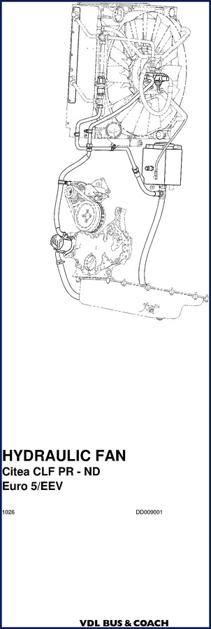
VDL BUS & Coach Citea CLF PR – ND, Citea CLF 120-255, Citea CLF 120-310 Technical Manual
If you are wrenching on a VDL BUS & Coach Citea CLF PR – ND, Citea CLF 120-255, Citea CLF 120-310 Technical Manual subject, you already know that aftermarket information is garbage for these buses. I have seen guys chase a fan-drive hydraulic leak for half a shift because some third-party PDF told them the wrong port size. This factory manual—68 pages, straight from VDL—is what you put on the bench when you want to get the job done and not come back next week.
The book starts with Foreword and Disclaimers, then hits Technical Information covering both Mechanical Components (Section 1.1) and Electrical Components (Section 1.2). Safety Instructions come next—Section 1.2.1 on Working with Hydraulic Liquids and 1.2.2 on Topping up/refilling. If you ever get curious about hydraulic fluid and skip the safety pages, you deserve the skin rash. Section 1.5 on Inspection and Maintenance is your reminder that these buses do not tolerate neglect.
Diagnosis: Hydraulic and Electrical
Diagnosis chapter splits into Hydraulic (Section 1.1) and Electrical (Section 1.2). The hydraulic side walks you through pump, oil, and motor checks. The electrical side covers everything from sensor inputs to control unit logic. Need to trace a wiring fault on the proportional valve? This chapter tells you the signal path without having to guess at pinouts. Page 26 of the diagnosis section is where I live when a fan drive acts up—factory scope patterns, not some translated guesswork.
Fan Drive System Description
The Fan Drive chapter is the meat of this manual. General information (Section 1) gives you hydraulic and electrical component overviews. System description (Section 2) includes the hydraulic schematic diagram (2.1.1), operation of the hydraulic fan drive (2.1.2), layout of the system (2.1.3), and even the fan-to-engine speed ratio (2.1.4). Electrical side covers controlling the proportional valve Y026 (2.2.1), software in the VFC (2.2.2), and operation of the BODAS unit (2.2.3). If you need to understand how the VFC talks to the gearbox ECU, this section has the signal flow. No guesswork.
Component Description: Sensors and Electronic Units
Section 3 lists every sensor and controller on the bus: Vehicle speed sensor B200, coolant temperature sensor B236, intake air boost pressure and temperature sensor B239, oil level sensor B023, DTCO tachograph P102, DMCI electronic unit A031, BODAS unit A039, E300 gearbox unit A051, VFC vehicle function unit A001, proportional valve Y038, thermostat valve, gear pump, gear motor. Having the actual part numbers and pin assignments from the factory means you can order the right replacement instead of cross-referencing a fourth aftermarket catalog. For related buses, check the VDL BUS & Coach SB 3000, SBR 3015, SB 2750 Operators Manual – 109 pp and the VDL BUS & Coach EST46/EST146 Diagnostics Manual – Pitcat Screens if you need deeper diagnostic trees. There’s also the VDL BUS & COACH Fan Drive Service Manual SB(R) for additional fan-drive-specific procedures.
Inspection and Adjustment Procedures
Section 4 gives you inspection steps: fluid level (4.1), lines and hoses (4.2), fan condition (4.3), temperature sensor check (4.4). Section 5 covers removal and installation of battery terminal clamps (5.1), hydraulic motor (5.2), hydraulic pump (5.3), and return filter element (5.4). Drain and fill procedure in section 6—if you do not follow the exact sequence for bleeding the hydraulic fan circuit, you will get aeration and cavitation that eats pump bearings. I have seen it.
Why This Manual Beats Aftermarket Copies
This is an original VDL factory document, not a third-party rehash. The safety warnings are written for the specific hydraulic pressures and electrical loads of these buses. The hydraulic schematic diagram is VDL’s own, with correct component labels. Aftermarket manuals often swap part numbers or skip the software flow for the VFC/BODAS units. Here, you get the actual 2018–2020 calibration logic. For a deeper dive into the engine systems, refer to Internal Combustion Engine basics or Manual Transmission if you are swapping gearboxes.
- Does this manual cover the entire HVAC or just the fan drive?
- It covers the hydraulic fan drive system only—not the full HVAC. If you need the cabin climate control or air conditioning, that is a separate manual. This one focuses on the hydraulic fan motor, pump, valves, sensors, and the electrical control from the VFC and BODAS units.
- Are torque specs included for the hydraulic motor bolts?
- Torque values are stated in the removal/installation sections. For the hydraulic motor mounting bolts, refer to Section 5.2 where the manual specifies the tightening sequence and value. Do not use generic fastener torque charts—use the factory numbers from this manual.
If you are tired of stopping mid-job to call a dealer hotline or dig through five different PDFs, this is the one. Download the Factory Manual and keep it on your shop tablet. Your come-backs will drop, and your customers will stop complaining about fan noise at the depot.

William H. –
I am very pleased with this manual. The PDF is high resolution. Contains clear bolt torque specs for VDL BUS & Coach. Worth every penny.
Alex K. –
Highly recommended! The pages are clean and well indexed. Contains detailed wiring diagrams for VDL BUS & Coach. Worth every penny.