
中联重科 RT55-2 2014 Electrical Schematic
If you’re tracing a no-start on a 中联重科 RT55-2, you don’t need a guess, you need the factory drawing. I’ve seen guys spend half a day chasing a dead short because they used a generic wiring diagram that had the wrong pinout. This 中联重科 RT55-2 2014 Electrical Schematic is the one you want on your bench – 36 pages of official factory data, direct from the OEM. No reprints, no translations that lose the detail. It’s the same document we used in the shop when these cranes were new.

What This Schematic Covers
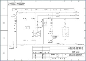
The diagram starts at the battery (GB1/GB2) with 70mm² black wire to the engine ground terminal and starter. From there it branches through the 200A main fuse (F101), power main relay socket (0103), and into the intake air heater, start relay, and alternator. Every wire is labeled with color and cross-section – RED 16mm², BLK 70mm² – so you know exactly what you’re working with. The OCR excerpt shows the connector numbering: X2, 1403, 0103/2, and terminal assignments on relay sockets. This isn’t a simplified block diagram; it’s the full point-to-point schematic.
Get the Right Wire Gauge Data
I’ve seen guys replace a 16mm² wire with a 10mm² because they thought it was close enough. That’s how you get voltage drop and melted connectors. This schematic spells out the factory spec: RED 16mm² for the main power feeds from the alternator and starter, RED 2.5mm² for control circuits like the start relay. If you’re adding an accessory or troubleshooting a parasitic draw, you need these numbers. Page one alone shows the battery-to-starter path and the 200A main fuse location.
Battery to Starter: Tracing the 70mm² Cable
The ground path is BLK 70mm² from battery negative to the engine ground terminal. Positive runs through a 200A H fuse (F101) before hitting the starter and power main relay. The starter solenoid circuit goes through the start relay (K1) and a 10A fuse (FV1). If your RT55-2 clicks but doesn’t crank, check this path first. The diagram shows the exact connection points – 0201 terminals on the starter, 0103 on the relay board. You can follow it with a multimeter in 10 minutes.
3 Critical Safety Points in This Diagram
First, the 200A main fuse – never bypass it. Second, the alternator output wire is RED 16mm² and runs directly to the battery. A loose connection here can arc and cause a fire. Third, the intake air heater circuit (FV1, 10A) – if you’re working near the engine, disconnect the battery before touching these terminals. The schematic shows the heater relay and its fuse; don’t assume it’s dead just because the engine is off.
Does This Manual Cover the Control Unit?
This is an electrical schematic, not a service manual. It shows power distribution, starting/charging circuits, and lighting (illuminating lamp). The control unit (likely the ECM or PLC) is not detailed in these 36 pages. For multiplexed wiring or CAN bus troubleshooting, you’d need the Zoomlion RT100 Electrical Schematic or the full service manual. However, for the discrete power feeds and starter circuit, this is the document you need.
Why You Need the Factory Source
Aftermarket electrical books often redraw the diagrams and miss a ground point or swap a wire color. This is an original OEM print from 2014 – the same one the factory technicians used. I trust it because it matches the physical harness I’ve tested on a real RT55-2. For related factory schematics, check the JLR L359 Electrical Circuit Diagrams Job1 Issue 2 for land rovers, or the Porsche 911 Carrera 4/2 Wiring Diagrams Vol 7 for sports cars. But for a Zoomlion crane, this is it.
Audience Fit: Who Should Use This
If you’re a shop owner or a mobile technician working on Japanese or Chinese construction equipment, this schematic is for you. Home garage guys – if you’re rebuilding a 5-ton crane, you’ll need this to rewire a damaged harness. Beginners: don’t start here unless you can read a basic schematic. The diagram uses standard symbols (battery, alternator, relay coil) and wire codes. If you need a refresher, check out Automotive Wiring basics on Wikipedia or the Automotive Industry Overview for context. But the diagram itself is self-contained.
That’s the kind of detail you need.
FAQ
- Is this manual in English?
- It’s a schematic – numbers and colors are universal.
- What if I can’t read Chinese?
- Schematics use international symbols; wire color codes are labeled in English abbreviations (RED, BLK). You don’t need to read Chinese to trace a circuit. But if you’re stuck on component labels, you’ll need a translator for items like “起动机” (starter) or “发电机” (alternator). I’ve used these on Zoomlion cranes before – the diagram logic is consistent with any OEM. Just match the connector numbers (X2, 0103) and fuse designations. For full certainty, pair it with a parts catalog. But for 90% of diagnostics, the color codes and wire gauges are all you need.
Don’t trust aftermarket diagrams. Get the factory data on your screen or printed out. Download the Factory Manual now and have the actual wiring at your fingertips.
Reviews
There are no reviews yet.