Alfa Romeo Spider 1982 Wiring Diagram
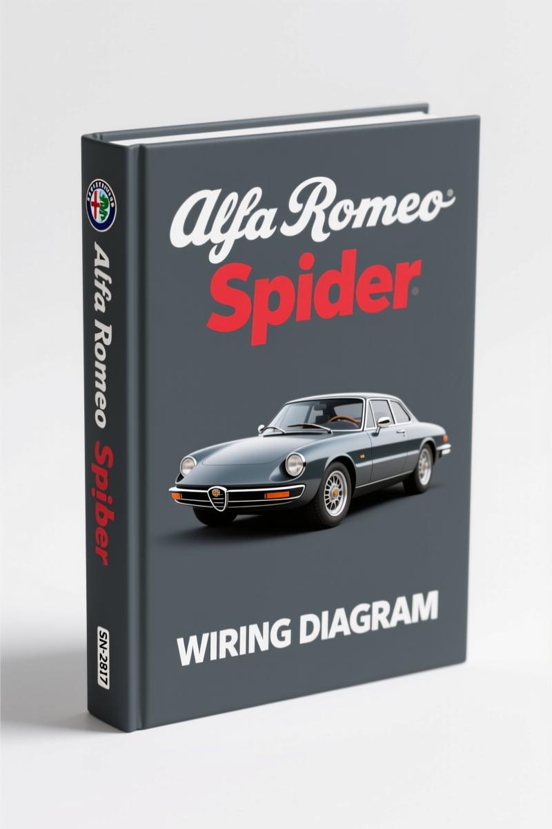
If you are chasing a short on a 1982 Alfa Romeo Spider and an aftermarket diagram shows a white wire where the factory ran blue, you are burning billable hours. This is the real thing – the actual OEM wiring diagram printed in 1982 by Alfa Romeo for the Spider 2000. 14 pages, no redrawn nonsense. It gives you the exact wire colors, connector codes, and component locations straight from the factory floor. You want to know which pin on the ignition switch feeds the cooling fan relay? It is on page 1. You need to verify the starter circuit for the automatic transmission? Page 2. The manual does not guess and neither should you.
Ignition, Starter, Alternator, and Engine Cooling Fan Circuits (Page 1)
Page 1 covers the heart of the electrical system. The ignition coil, breakerless distributor, alternator, battery, fuse box, and the engine cooling fan circuit are all drawn with their factory wire colors and connector designations. The cooling fan thermo switch is tagged with part number 01121. The power window relay? Tagged 90612. Every component has an index number that matches the component board on page 13. If you are swapping a Spider engine into another chassis, you need this page to wire the alternator correctly. Do not rely on a generic wiring schematic – the Spider uses a unique L Blue/Red wire from the alternator to the charge indicator. You will not find that in a Chilton’s book.
Starter Circuit for the Automatic Transmission Spider
Automatic transmission Spiders have a separate starter relay and a seat belt buzzer relay that interacts with the starter circuit. Page 2 of this manual maps the entire path: from the ignition switch (03300), through the starter relay (00681), to the starter (00400), with notes on the back-up light switch and gear selector light. Note the wire routing reference – the manual points you to page 8 for the actual routing diagram. That kind of cross-referencing saves you from running a new wire to the wrong harness. If your Spider has a manual transmission, you still get the correct starter circuit on page 1. The automatic page is additional – not a replacement.
High and Low Beams: Factory Wire Colors and Ground Points
The headlight circuit on the Spider uses a separate lighting switch and a high/low beam switch. Page 3 shows the left and right high/low beam assemblies (01704, 01705) with their ground connections at G1 and G2. The manual tells you that the left high beam wire is Green/Black from the fuse box, and the right low beam is Gray from the same source. If you are retrofitting H4 bulbs or troubleshooting a dim headlight, these factory color codes are your only reliable reference. The high beam indicator (02302) on the speedometer cluster is fed by a Blue/Black wire – not the generic Blue you might expect. That kind of detail only comes from an OEM source.
Component Index and Connector Code – Why Page 11 and Page 12 Are Worth Their Weight in Diagno
Page 11 is a component index that lists every numbered component in the diagrams followed by its description. Page 12 gives you the connector code – what each connector housing looks like and which cavities are used. If you are trying to find the connector for the seat belt warning module (00718), you look up the number in the index, then cross-reference the connector code to see which terminal positions carry power. This is the difference between a 10-minute pin-out and a 2-hour headache. Aftermarket diagrams often omit connector maps or simplify them into generic blocks. This manual does not. Every wire termination is accounted for.
Fuel Injection System Circuits – Covered on Pages 9/10
The 1982 Spider 2000 uses Bosch L-Jetronic fuel injection, and the factory wiring for it is on pages 9 and 10 of this manual. These pages show the fuel injection system circuits, including the ECU connections, injector wiring, and the air flow meter signal. If your Spider cranks but does not start, and you suspect a wiring fault in the injection harness, this is where you start. The diagram includes ground points, power feeds from the main relay, and the exact wire colors for each injector. You will not find this level of specific information in a generic wiring book. It is Alfa Romeo’s own diagram, exactly as it left the factory.
How This Manual Compares to Aftermarket Diagrams
I have seen aftermarket diagrams for the Spider that merge the manual and automatic transmission starter circuits into one confusing mess. This manual keeps them separate. I have seen reprints that swap the wire colors for the turn signals. This manual gives you the correct Gray/Red and Green/Black for the left and right turn signals (page 5). The factory manual also includes a connector code page (page 12) that lists which terminals are used – something aftermarket sellers often leave out. If you want to repair your Spider’s electrical system without creating new problems, use the OEM diagram. Anything else is a gamble.
Related Manuals
- Alfa Romeo 33 Wiring Diagram – DIY 4×4 Switch Guide (38 Pages)” target=”_blank”>Alfa Romeo 33 Wiring Diagram – DIY 4×4 Switch Guide (38 Pages)
- Alfa Romeo 33 Wiring Diagram – Factory Electrical Schematics” target=”_blank”>Alfa Romeo 33 Wiring Diagram – Factory Electrical Schematics
- Alfa Romeo 33 Installation Manual – A/C Factory Specs for 1.3, 1.5, 1.7 i.e.” target=”_blank”>Alfa Romeo 33 Installation Manual – A/C Factory Specs for 1.3, 1.5, 1.7 i.e.
For more background on automotive wiring principles, see Automotive Wiring” target=”_blank”>Automotive Wiring and Automotive Wiring” target=”_blank”>Automotive Wiring.
Frequently Asked Questions
- Is this the correct wiring diagram for a 1982 Spider 2000?
- Yes. This is the original factory wiring diagram for the 1982 Alfa Romeo Spider 2000. It covers both manual and automatic transmission models. The document is titled “124 Spider 1982 Wiring Diagrams” and was published by Alfa Romeo.
- Does it include the fuel injection system circuits?
- Pages 9 and 10 of the manual are dedicated to the Bosch L-Jetronic fuel injection system circuits. You get the ECU, injectors, air flow meter, and all associated wiring with factory wire colors.
- Can I use this for a manual transmission Spider?
- Absolutely. The manual includes both the manual transmission starter circuit (page 1) and the automatic transmission circuit (page 2). The rest of the diagrams are the same regardless of transmission type.
- What format is the manual in?
- The manual is a digital PDF download, 14 pages, scanned from the original 1982 factory document. It is not a reprint or a third-party redraw. You get the exact pages as printed by Alfa Romeo.
Get the wiring right the first time. Download the Factory Manual and keep a copy in your shop. Your Spider will thank you when the turn signals actually flash the correct color.



Reviews
There are no reviews yet.