1989 Service Manual – International 1000-8000 Instruments
You’ve got a dead gauge or a speedometer that quit reading. You pull the cluster and find three circuit boards and a bunch of pins. Without factory wiring pinouts, you’re guessing. That costs time and sometimes a fried board. This 1989 Service Manual is the original Navistar print — 24 pages covering exactly what you need: cluster removal, gauge tear-down, printed circuit testing, and the microprocessor programming sequence for the speedo and tach. No aftermarket fluff, just the step sequence the factory used.
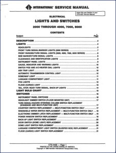
I’ve seen guys skip the static discharge step on page 3 and toast the entire cluster. The manual calls it out clear: “Static electricity can cause permanent damage. Touch grounded metal before handling.” You won’t find that warning in a generic reprint. This is the real deal — scanned from the CTS-4408F section that replaces the old CTS-4001 manual.
Instrument Cluster Removal and Circuit Boards
Page 2 starts with the instrument cluster description. It’s a demountable package held in place by clips and connectors. The manual walks you through pulling the whole cluster in about five steps. Then it shows how to separate the three printed circuit boards from the back — each one handles specific gauge groups. If you’ve got a fuel gauge that reads wrong but the temp gauge is fine, you can swap just the affected board instead of the whole assembly. The ignition must be OFF, not ACC, to avoid shorting the ground and ignition pins. That’s page 3.
Printed circuits are covered on page 4. The manual includes the connector pin assignments — critical for diagnosing open traces or corroded contacts. Without these, you’re probing blind.
Speedometer Programming: Calculation and Switch Settings
On page 6 you get the SPEEDOMETER PROGRAMMING, CALCULATION, AND SWITCH SETTINGS CHART. This is a full table that tells you which dip-switch combination matches your tire size, axle ratio, and transmission output. If you’ve swapped a differential or changed tire diameter, you program the speedo via these switches. The chart covers all common ratios for the 1000 through 8000 series. Miss one switch and your odometer will be off by 10% or more. Page 6 is where you get the exact settings. No guesswork.
Cluster Failure Diagnosis: Where to Start
Pages 12–16 lay out a systematic failure diagnosis. It breaks down by symptom: air/oil pressure gauge failure, electrical temp/fuel display failure, voltmeter/pyrometer failure, speedometer/odometer/tachometer/hourmeter failure, and mechanical water temp failure. Each section starts with the harness connector inspection at the cluster (page 12) and works through the sensor inputs. For the microprocessor gauges, the manual tells you to check the voltage at specific pins before condemning the board. That alone can save you from replacing a $300 cluster when the problem is a corroded pin at the bulkhead.
One note: the gauges don’t return to zero when power is removed. That’s normal. If you see a needle stuck at a reading with the key off, don’t panic — it’s designed that way. The failure diagnosis tables tell you what voltage ranges are acceptable on the circuit board test points.
Floscan: Calibration and Testing
Pages 17–21 cover the Floscan fuel flow meter system. This is a separate module that measures fuel consumption. It has its own sensor, calibration procedure, and test sequence. The calibration routine on page 20 requires a measured fuel volume and a known distance. You enter the data via the control unit. The manual gives the exact steps for entering calibration mode and validating the output. If your fuel economy readout is junk, this is the section you need. Page 21 has a testing procedure using a multimeter to verify the sensor pulse rate.
Source Authenticity – OEM vs. Aftermarket
This is an original Navistar International publication, copyright 1989. Not a photocopy of a copy. Not a PDF rebuilt from a third-party database. Every page matches the factory CTS-4408F revision. If you’ve ever tried to diagnose a International cluster using a Haynes or an online forum, you know the pain of missing switch settings or connector pinouts. This manual gives you the exact connector view from page 13 — cluster connectors with pin numbers and circuit functions. That’s the difference between a repair that takes an hour and one that takes two days of backprobing wires.
For reference on how a manual transmission interacts with the speedometer sensor, see the Manual Transmission section in the factory drivetrain manual. Also check Manual Transmission for shift pattern diagnostic info if your speedometer reading is erratic due to a failing transmission output speed sensor.
- Does this manual cover the full International 1000-8000 series?
- Yes, it covers 1000 through 4000, 7000, and 8000 series vehicles. It is a supplement to the CTS-4001 service manual, replacing section CTS-4408. It specifically addresses the instrument cluster, speedometer, tachometer, hourmeter, and Floscan system.
- What torque specs are included?
- None. This is an electrical and electronics manual. There are no fastener torque values. For engine or driveline torque specs, you need the base service manual.
If you’re working on an International instrument cluster and need the factory programming codes for the speedometer, the static discharge warning, and the printed circuit board test points, get this 24-page manual on your bench. It’s the only source that matches the factory switch settings chart from 1989. Download the Factory Manual now.

John D. –
I am very pleased with this manual. Quick download after payment. It helped me to rebuild my vehicle 1989 electrical connector. Highly recommended for mechanics.
Charles W. –
Perfect factory service manual. The scan is high-quality and easy to navigate. Every torque spec is included for vehicle 1989. Saved my weekend project! Thank you.