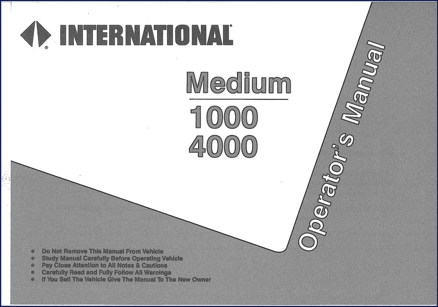
1994 Troubleshooting Manual – International 1000/3000/4000 FBC Electrical System
You’ve got a 1994 Troubleshooting Manual here – 260 pages of factory electrical diagrams and diagnostic procedures for International 1000, 3000, and 4000 FBC trucks. Navistar printed this in 1994, and if you’re chasing a no-start, a brake light that won’t go out, or a dead charging system, this is the document that keeps you from replacing parts by guesswork. Section numbers match the factory layout: A through J. Each section hands you the circuit operation, component locations, and a step‑by‑step diagnostic routine. Aftermarket manuals skip the ground paths and relay pinouts; this one doesn’t.
Section A covers connector repair – the correct way to replace terminals and pins without damaging the harness. I’ve seen techs splice wires because they didn’t have the pin‑removal procedure. That’s a fire waiting to happen. Page A‑1 walks you through the tool list and the disassembly order. Follow it.
Power Distribution and Grounds – Section B
Section B, Power Distribution and Grounds, is where most electrical problems live. Bad grounds cause more intermittent failures than failed components. This section shows you the factory ground points, the power feed paths, and how to voltage‑drop test each circuit. The diagrams are clean – you can trace from battery positive through the fuse block to the load. Stop guessing which wire is the ground. It’s on page B‑1.
1994 Troubleshooting Manual: Engine Shutdown and Glow Plugs
Section D is Engine Shutdown. Section E covers Glow Plugs, Wait to Start Light, and Ether Start. If your International won’t crank after a cold soak, you’ll use these two sections together. The manual explains the glow‑plug relay control circuit and the engine shutdown solenoid operation. Don’t throw parts at it – test the control side first. The wiring diagram for the shutdown circuit is right there, with voltage readings at each connector. Same for the glow plugs – page E‑1 has the resistance check procedure.
Brake Systems – Section I: What You Need to Know
Section I covers Brake Systems, Warning Lights, Park Brake, Air Dryer, and Heated Drain Valve. If the brake warning light stays on or the air dryer cycles constantly, this section gives you the switch logic and pressure‑switch testing sequence. The park brake circuit is tied into the start inhibit logic – if the brake isn’t released, the starter won’t engage. That’s a common misdiagnosis. Page I‑1 lists the component locations and the test steps for each switch. I’ve used this to clear a “brake” warning light in under 15 minutes because I knew which pin to ground.
Diagnose Starting and Charging with Section C
Section C – Batteries, Charging and Starting. You need the charge pressure? Page C‑1. The starter solenoid circuit? Section C has the exact wire colors and connector views for the International 1000/3000/4000. Watch for the ground at the starter – if it’s loose, you’ll get intermittent cranking. This manual shows you the torque spec for the battery terminals (check the intro section, page 1). Don’t guess the spec; use the factory number.
Section G covers Backup lights, Horn, Marker/Park Lights, Stop Light Switch, Turn Signals/Hazard. Section F handles Headlights, Daytime Running Lights, and Fog Lights. If your turn signals flash fast or the horn doesn’t work, section G has the flasher circuit and the steering column wiring. Aftermarket diagrams often swap the left and right circuits – not here.
Section J is Allison WT Transmission, Engine Brake, and Two‑Speed Axle. Transmission shift complaints often trace back to a bad speed sensor wire. The manual includes the transmission control circuit and engine brake interlock. If you have a two‑speed axle that won’t shift, check the switch and the solenoid wiring using the diagram in section J.
Source Validity – Why OEM Factory Manuals Win
This is a Navistar‑published document, not a third‑party reprint. The copyright is 1994, the part number CTS‑5111 is on every page. I’ve seen aftermarket troubleshooting guides that reuse generic wiring symbols and miss the specific International relay numbering. This manual uses the actual ISO relay pin numbers (85, 86, 30, 87, 87A). That matters when you’re probing a relay socket under the dash and need to know which terminal is power and which is ground. The intro section (page 1) explains the relay control coil operation and the key switch positions. If you’re working on an International 1000, 3000, or 4000 FBC, this is the correct source.
- Can I use this manual for a 1995 International 4000?
- No. This is for 1994 model year FBC trucks. Electrical changes happen year to year.
- What makes this different from a generic electrical book at the auto parts store?
- Generic books give you one wiring diagram that’s supposed to cover five years of trucks. They skip the component location charts and the diagnostic logic sequence. This manual has separate sections for each system – brake, engine shutdown, glow plugs, transmission. Each section starts with a description of how the circuit operates, then shows the diagram, then gives you a step‑by‑step test procedure. For example, the brake system section includes the park brake switch adjustment and the air dryer heater test. A generic book won’t tell you which wire at the brake switch is normally open. This does, because it’s the factory document Navistar technicians used.
If you’re tired of guessing which wire goes where or replacing parts that test good, get the real thing. Download the Factory Manual from AutoRepairManuals and keep it on your tablet next to the truck. For related electrical guides, check out Volvo BM Michigan 850 1995 Troubleshooting Manual, Volvo BM Michigan D6B-D16B Troubleshooting Manual – 144 Pages, and Hitachi 140W-3 2007 Troubleshooting Manual – 618 Pages. For background on manual transmission diagnostics, see Manual Transmission and Manual Transmission.
Reviews
There are no reviews yet.