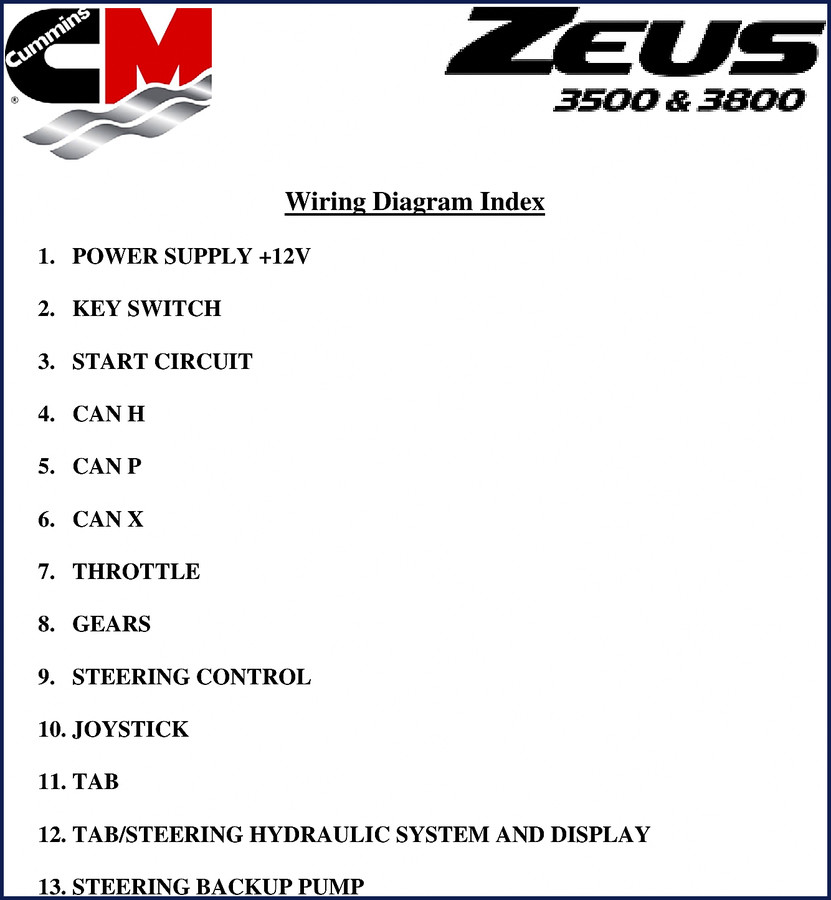
Cummins 3500, 3800 Wiring Diagram – Factory OEM 14-Page Manual
You are pulling your hair out over a no-crank on a Cummins 3500 or 3800? I’ve seen it too many times. Guys start swapping parts because they can’t read a wiring diagram that was copied twice and lost half the colors. This is the factory wiring diagram. 14 pages. Not a reprint. Not a third-party scan. The exact PDF that Cummins released for the ZEUS platform. The Cummins 3500, 3800 Wiring Diagram is what you hold – every circuit, every termination, every wire color from the OEM.
Power Supply +12V: Where the Circuit Starts
Page 2 of this diagram shows the +12V power supply routing from the battery through the main relay, helm harness, and VIP modules. If you are getting voltage drop at the ECM, trace back through the power harness connections shown on that page. The manual indexes each wire color – Rd/blk, Prpl, Blu – so you can verify continuity without guessing.
CAN Networks – H, P, and X: What Each Bus Handles
Three CAN buses run through these engines. CAN H, CAN P, and CAN X. Each serves a different function – engine control, vessel systems, and auxiliary. Page 5 shows the termination resistors (120 Ω) and the wiring to the SMM, VIP, and helm displays. If you have intermittent communication faults, check those terminations first. I’ve fixed more than one ghost issue by finding a missing resistor.
Start Circuit: The Path from Key to Crank
The start circuit on these Cummins units uses a key switch and a start-stop panel. Page 4 lays out the starter solenoid, starter mag switch coil, and the neutral safety input from the shift lever. If the engine won’t crank, verify the jumper wire between the CCM and the starter relay. The diagram shows the exact pin numbers – do not bypass the neutral safety switch unless you want the boat to launch through the garage door.
3 Critical Systems That Require Accurate Wire Tracing
Number 1: the throttle system. The wiring diagram dedicates a section to THROTTLE, which connects the helm controller to the ECM. One crossed wire and the engine runs wide open. Number 2: the steering control – joystick, tab, and backup pump. The TAB/STEERING HYDRAULIC SYSTEM AND DISPLAY section on page 12 shows how the VesselView and autopilot interact. Number 3: the gear solenoids. Forward and reverse solenoids are powered through a 30A circuit. Page 2 shows the exact relay positions.
What This 14-Page Wiring Diagram Actually Covers
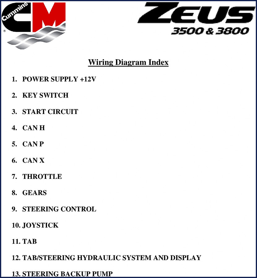
It covers the Cummins 3500 and 3800 (ZEUS) wiring for all major systems: power supply, key switch, start circuit, CAN H, CAN P, CAN X, throttle, gears, steering control, joystick, tab, tab/steering hydraulic system and display, and steering backup pump. That is 13 indexed sections across 14 pages. Every wire color code, every connector pin, every termination resistor value is from the factory. No aftermarket re-draw.
Why OEM Wiring Beats Aftermarket Harness Drawings
I have a stack of aftermarket manuals on my shelf that I use for doorstops. They swap wire colors, leave out termination resistors, and simplify CAN bus routing until it’s useless. This is a direct factory PDF. If you work on marine or industrial Cummins engines, you need the real thing. For other Cummins platforms, see Cummins QSK19 QSK38 QSK50 QSK60 2010 Wiring Diagram | Factory OEM and Cummins Onan RBAB 6kW-15kW 2013 Operators Manual | OEM Factory Specs. Also Cummins Onan P216G-OL20 Parts Manual 2010 if you need parts breakdowns.
Audience Fit – Who Needs This Diagram?
DIY boat owners with a Cummins 3500 or 3800 inboard. Marine mechanics who need a quick reference trace for CAN faults. Workshop owners who want to stop burning billable hours on electrical diagnosis. If you are new to automotive wiring, read up on basic Automotive Wiring principles first, then come back to this. The diagram assumes you know the difference between a relay coil and a contact. If you do not, find a mentor or watch a reputable Automotive Wiring video before you start cutting wires.
Frequently Asked Questions
- Does this manual cover the 3800 model?
- Yes. The diagram applies to both 3500 and 3800 ZEUS engines.
- What specific wire colors are referenced in the start circuit?
- Page 4 shows the start circuit with a Prpl wire from the key switch to the Halon breakout and then to the CCM. The starter solenoid uses a jumper wire. The diagram also references Rd/Blk wires for power. All colors are listed with their exact positions. You must have a printer or tablet to view these – the PDF is clear but small details matter. Do not rely on a phone screen for wire tracing.
You know what is worse than a no-start? A half-page generic diagram that leaves you chasing ghosts. This is the factory document. 14 pages of actual wiring from Cummins. If you diagnose a single circuit wrong, the labor costs more than this PDF. Cummins QSK19 QSK38 QSK50 QSK60 2010 Wiring Diagram | Factory OEM and Cummins Onan RBAB 6kW-15kW 2013 Operators Manual | OEM Factory Specs and Cummins Onan P216G-OL20 Parts Manual 2010 are related – but this one is specific to the 3500/3800. Download the Factory Manual now, print it, and keep it in the engine room.
Reviews
There are no reviews yet.