Freightliner M2 2012 Wiring Diagram – Factory OEM Manual
I’ve lost count of how many times I’ve seen a guy chase a short for three hours because he was using a generic wiring diagram that had the pinout wrong. That doesn’t happen with this manual. This is the actual factory document – 43 pages, direct from Freightliner, for the 2012 M2. If you’re working on a Business Class M2 and you need to know exactly where power comes from and where it goes, this is the only piece of paper you should have on your bench.
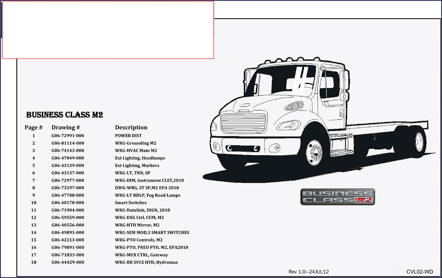
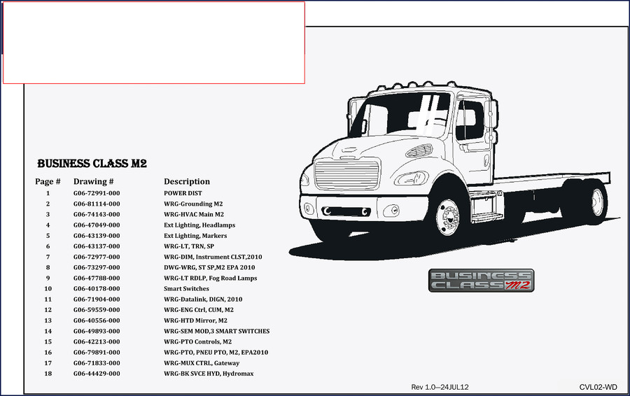
The table of contents tells you everything you’re getting: Power Distribution (drawing G06-72991-000), Grounding for the M2, HVAC Main, Exterior Lighting – headlamps and markers, Turn Signals and Stop Lamps, Dimming and Instrument Cluster, the Stop Lamp circuit for EPA 2010, Fog and Road Lamps, Smart Switches, Datalink and Diagnostic Network, Engine Controls for Cummins, Heated Mirrors, the SEM Module with three smart switches, PTO Controls, Pneumatic PTO for EPA 2010, MUX Control Gateway, and the Hydromax Brake Service Hydraulic system. That’s 18 separate drawings in one document.
Power Distribution System – EPA2010
Page 2 of the PDF lays out the high-current distribution in a way that makes sense. You’ve got a 175A fuse for the main powernet, two 125A fuses for secondary feeds – all routed through the Primary Powernet Distribution Box (PNDB). The wire sizes are listed in both metric (mm²) and AWG, which is what I expect from a proper factory drawing. Need to know what feeds the ABS module? It’s called out as MOD330 right on the schematic, with the exact fuse position and wire gauge. No guesswork.
HVAC Wiring – M2 Main
Section 3 covers the HVAC system (drawing G06-74143-000). If the blower motor quits or the A/C clutch won’t engage, you can trace the power path from the PNDB through the HVAC module (MOD703) to the compressor and fan. The manual shows the ground paths, too – a lot of aftermarket diagrams skip grounding, which is how you end up with intermittent failures. This one shows every ground point on the chassis.
Smart Switches and the SEM Module
Sections 10 and 14 cover the Smart Switches and the SEM Module with three smart switches (G06-40178-000 and G06-49893-000). These multiplexed switch packs control everything from lights to power take-off. If you’ve got a switch that works sometimes and not others, you need to see the internal logic and the input/output pins. The factory diagram shows the exact connector views and signal names – not a generic block diagram. I’ve used this to diagnose a dead headlamp switch on an M2 that turned out to be a bad ground at the module, not the switch itself.
PTO Controls – Pneumatic and Electric
Two sections deal with PTO: one for standard controls (G06-42213-000) and one for the pneumatic PTO on EPA 2010 models (G06-79891-000). If you’re retrofitting or troubleshooting a PTO that won’t engage, the manual gives you the full wiring for the control switches, solenoids, and the ECM interface. Section 15 shows the electric PTO circuit; section 16 shows how the pneumatic version interconnects with the air system and the engine controller. Both are referenced to the 2010 EPA emissions config, so you know the pinouts are correct for that year.
Source Validity – OEM vs Aftermarket
This is not a reprint. This is the original factory PDF from Freightliner, part of the CVL02-M2 PrintPak, revision 1.0 dated 24JUL12. The drawing numbers all start with G06- and match Freightliner’s internal system. Aftermarket wiring diagrams often omit the smart switch logic or use generic symbols that don’t match the actual modules. If you want to see the actual wire colors and connector pin numbers as they come off the assembly line, this is it. I’ve compared aftermarket diagrams to this one, and they’re wrong often enough that I won’t touch them on a job. If you want to learn the basics of Automotive Wiring, that’s fine, but when you’re billing time, you need the real thing.
You can also pair this wiring diagram with the Freightliner M2, Century Class, Columbia, Cargo, FLA COE 2005 Service Manual for mechanical procedures, or the Freightliner M2 2012 Operators Manual – Factory Specs & Procedures if you need fluid capacities and dash controls. For another wiring schematic covering similar years, check out the Freightliner M2 Wiring Diagram.
Wiring Basics and Cross-Reference
If you’re new to reading these diagrams, spend some time on Automotive Wiring to understand the notation. The factory manual uses standard SAE symbols, but the callouts are specific to Freightliner modules. Every wire is labeled with a circuit number and color code – for example, you’ll see “14H # 1101 (R)” which means a red wire, 14 gauge, circuit 1101. That matches the truck’s actual harness. When you’re probing with a multimeter, you can verify from the diagram exactly what should be hot with key on, key off, and engine running.
Frequently Asked Questions
- Does this manual cover the engine control wiring for the Cummins ISB?
- Yes. Section 12 (G06-59559-000) covers WRG-ENG Ctrl, CUM, M2 – the engine control wiring for Cummins engines in the M2 chassis. All pinouts and connectors are included.
- What about the datalink and diagnostic connector?
- Section 11 (G06-71904-000) is the Datalink and Diagnostic Network drawing for 2010 models. It shows the J1939 and J1708 data bus connections, the diagnostic connector pins, and how the ECM, TCM, ABS, and body controller communicate. This is critical when you’re dealing with no-communication faults or wiring damage that interrupts the datalink backbone. The drawing covers 11 pages, with detailed routing through the chassis and each module’s interface. I’ve used it to restore communication on a truck that had a rubbed-through wire at the frame rail – the diagram showed exactly which splice pack to open and what color wires to look for.
If you’re working on a 2012 Freightliner M2 and you need the actual factory wiring, stop messing around with screenshots and photocopies. Download the Factory Manual – it’s the same 43-page PDF the dealer uses, and it’ll save you the headache of chasing ghosts in the harness.




Reviews
There are no reviews yet.