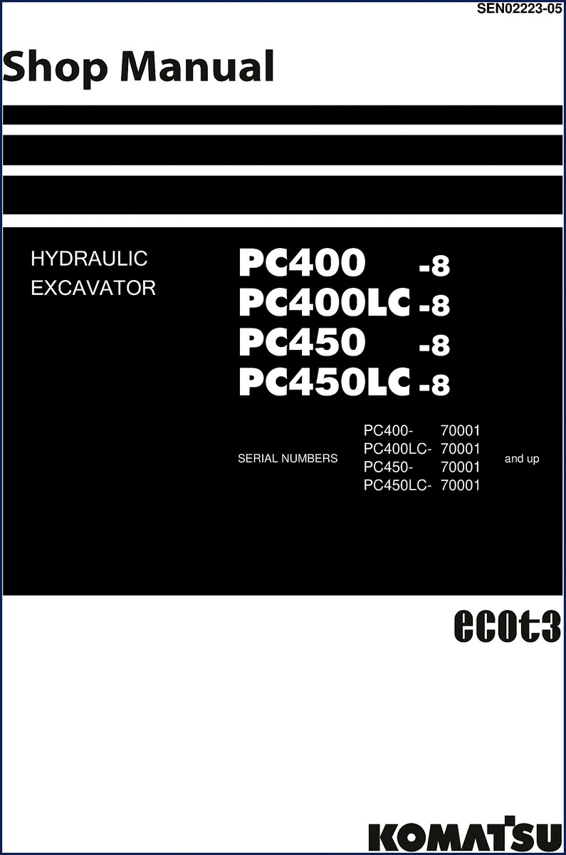
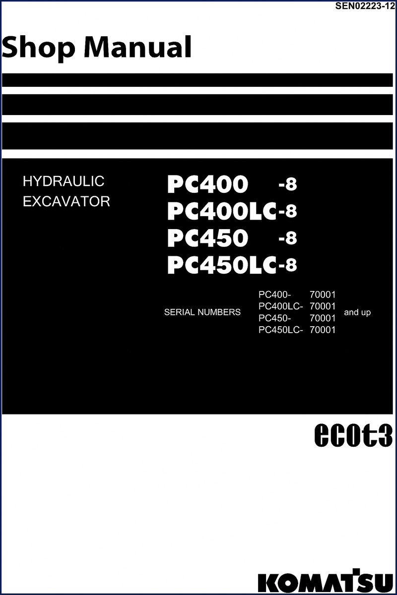
Komatsu PC400LC-8, PC450LC-8, PC400-8, PC450-8 Workshop Manual
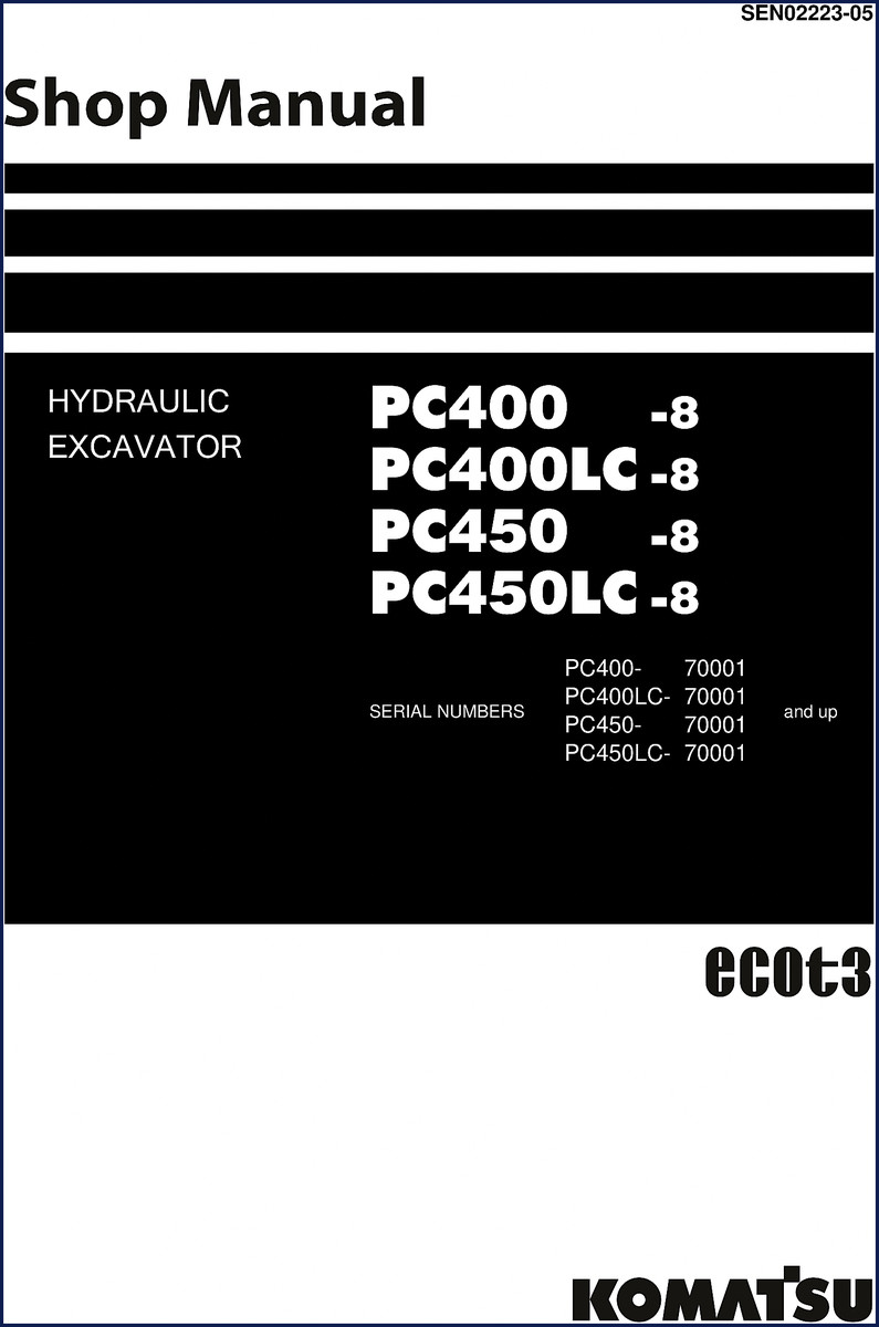
You ever get a job where the aftermarket manual tells you to torque the head bolts to “snug” and then walk away? That’s how engines crack and customers leave. This Komatsu PC400LC-8, PC450LC-8, PC400-8, PC450-8 Workshop Manual is the factory binder – 1055 pages of what the engineers wrote, not what some third-party translator thought was close enough. If you’re pulling a pump on a PC400-8 or setting the swing circle clearance on a PC450LC-8, you need the numbers that came from the test bench in Osaka, not a scanned reprint with missing tables.
Hydraulic System Coverage: What the Manual Actually Includes
Section 10 in this manual splits the hydraulic system into three parts. Part 1 covers the equipment layout, tank, filter, and the pump itself. Part 2 walks you through the control valve, CLSS logic, merge-divider valve, and holding valve. Part 3 dives into the PPC valve, travel motor, swing motor, and hydraulic cylinder disassembly. Need the charge pressure for the travel motor? Page 73 has the spec table. Don’t guess – if you set the relief wrong on a PC450-8, you’ll blow a seal and be down for a week.
Testing and Adjusting – Step-by-Step with Tool Lists
Section 30 is where this manual earns its keep. It lists every special tool you need – part numbers included – for testing engine speed, blow-by pressure, fuel system residual pressure release, and the PC control circuit oil pressure. The manual tells you to release residual pressure from the fuel circuit before cracking any line. That’s not a suggestion; it’s a safety step printed in bold. There’s a full procedure for adjusting valve clearance on the engine, plus a sketch of each special tool so you can fabricate or order the right one.
Standard Value Table for Engine and Chassis
Section 20 gives you the standard service values – compression pressure, boost pressure, exhaust temperature, and tolerances for the undercarriage. If your PC400LC-8 is pulling to one side, the track roller and idler specs are here. Don’t trust a generic hydraulic chart. Komatsu factory values account for the specific pump and control valve combination in these 8-series machines. Record your measurements and compare to the table on page [DATA NEEDED] – the manual tells you exactly when to replace vs adjust.
Electrical System and KOMTRAX Terminal
The electrical system chapter goes beyond basic wiring. It covers the engine controller, monitor system, sensors, and the KOMTRAX terminal. Need to test a solenoid valve output pressure? Section 30.1 describes the procedure with the machine’s monitor. The manual includes failure code tables and fuse locations in Section 40. When you get a code, you cross-reference it in the troubleshooting section rather than chasing ghosts with a multimeter. For basic transmission theory, see Manual Transmission resources – but for the actual drive components on this excavator, stick to the OEM book.
3 Reasons to Choose OEM Documentation Over Aftermarket
First, aftermarket manuals often omit the safety notices printed in the foreword of this manual – things like handling electric equipment and hydraulic component safety. Second, the torque table on page [DATA NEEDED] uses Komatsu’s own standard tightening torque, not a generic automotive chart. Third, the wiring diagrams are color-coded according to Komatsu’s wire code system. If you follow a knockoff diagram, you risk shorting the controller. Manual Transmission might help you understand gear principles, but for this machine’s electrical architecture, use the factory print.
Does This Manual Cover the Fuel System Thoroughly?
Yes. Section 30 includes handling fuel system parts, releasing residual pressure, testing fuel pressure, bleeding air, and checking for leaks. The EGR valve drive pressure test and cylinder cut-out operation are also documented. If you’re working on a common rail system, the specs are right there.
FAQ
- How do I test the PC control circuit oil pressure on a PC450LC-8?
- The manual specifies using a 5 MPa gauge connected at the pump PC port. You run the engine at high idle, operate the attachment circuit, and compare the reading to the standard value table in Section 20. The adjustment procedure is under “Checking and adjusting pump PC control circuit oil pressure” in Section 30.1. If the pressure is off, you remove the PC valve cover and turn the adjusting screw – but only after verifying the LS circuit pressure first. Skip that order and you’ll chase a ghost loop all day.
- Are the two-link pin torque specs included for the work equipment?
- Yes, they are in the “Dimensions of components” subsection under Work Equipment.
This factory manual gives you one shot at getting it right – the Komatsu specs, not a guess. If you want the full 1055 pages with searchable PDF, Download the Factory Manual from AutoRepairManuals today.
Related manuals you might need: Komatsu PC400LC-8 2011 Service Manual, Komatsu PC450LC-8 2011 Service Manual, Komatsu PC400-8 PC450-8 Workshop Manual
Reviews
There are no reviews yet.