You’ve been staring at a rat’s nest of wires on that Land Rover L319 2009 Wiring Diagram for two hours. The aftermarket diagram says pin 3 goes to the air suspension compressor, but you’ve got no continuity and a blown fuse. I’ve been there. Aftermarket schematics are guesses dressed up with clip art. This manual is the real deal – JLR Engineering’s own electrical circuit diagrams, released October 21, 2009. 165 pages of factory-correct paths, connector views, and component locations. If you’re working on the L319, this is the only wiring diagram you should trust.
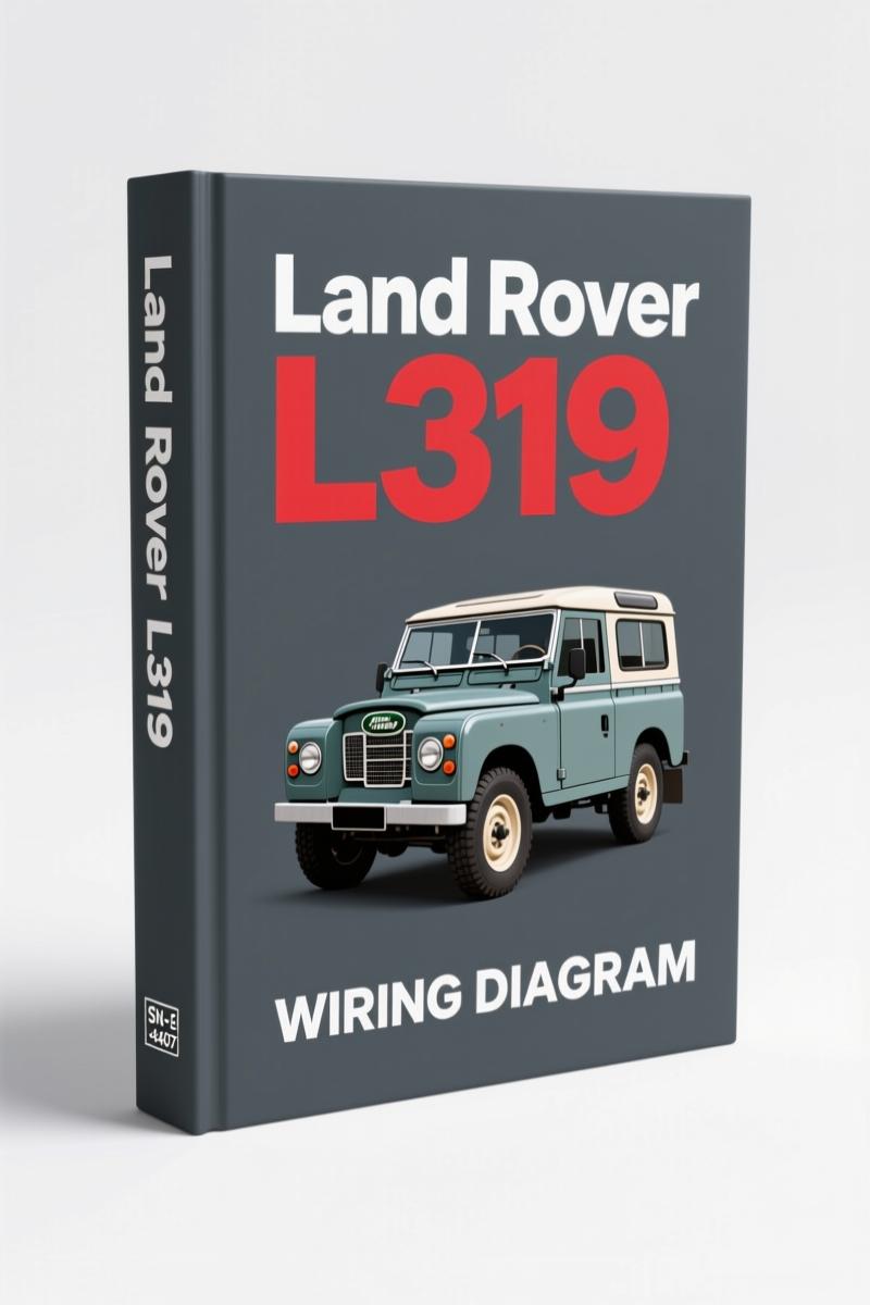
I’ve torqued head bolts on everything from a 2.5L diesel to a 5.0L supercharged V8. Wiring is where most diag time gets wasted. OEM torque specs? I know them cold. But electrical pinouts? That’s where the manual earns its keep. Page 2 shows the AIR SUSPENSION CIRCUIT – a system that loves to eat compressors and blow fuses if you chase the wrong wire. Page 43 gives you the ELECTRIC PARK BRAKE CIRCUIT – don’t guess the actuator wiring, or you’ll be replacing a controller module.
Air Suspension Circuit: Tracing the Compressor Relay
Land Rover air suspension on the L319 is notorious for relay burn and height sensor shorts. The manual has a dedicated section: AIR SUSPENSION CIRCUIT AH22-70180-A-A. You get the exact pinout for the compressor relay, the vent solenoid, and the pressure sensor. Part numbers are listed for the connector housings. If you’re swapping a compressor, you need to verify the relay coil circuit before you throw parts at it. Page 2 will save you three hours of guessing.
Architecture Overview – HS CAN, MS CAN, and MOST
Three network sections are laid out: ARCHITECTURE OVERVIEW HS CAN (page 7), MS CAN (page 15), and MOST (page 9). These are not generic bus diagrams. They show termination resistors, module splice points, and which control units talk to each other. If you’re diagnosing a no-start or a communication fault, start here. The HS CAN circuit diagram gives you the exact splice locations and wire colors. Aftermarket books skip this – then you spend an hour probing the wrong twisted pair.
Engine Management Diesel 3.0L Circuit – Pin Assignments
Four different engine management diagrams exist: Diesel 3.0L, Diesel V6 EU4, Petrol V6, Petrol V8. The ENGINE MANAGEMENT DIESEL 3.0L CIRCUIT AH22-70032-L-A covers the 3.0L TDV6. You get the ECM connector view with pin numbers and signal descriptions. Need to test the fuel pressure regulator? The diagram shows which pin goes to the PCM and which goes to chassis ground. No interpretation needed – it’s straight from JLR Engineering.
Power Distribution: Engine Compartment vs. Passenger Compartment
Two separate POWER DISTRIBUTION circuits: engine compartment (AH22-70010-A) and passenger compartment (AH22-70010-D). Fuse ratings, relay positions, and junction block internals are all drawn. I can’t count how many times I’ve seen a melted fuse box because someone used an aftermarket diagram that swapped the B+ feeds. This manual gives you the correct gauge and fuse ampacity. If you’re installing auxiliary lighting or a winch, these pages are your reference.
3 Reasons to Choose OEM Documentation
First: accuracy. Aftermarket diagram vendors re-color and re-label wires to avoid copyright. They break the color code. Second: connector views. OEM manuals include the shape and orientation of every connector. Third: revision control. This is the 10MY J1P90 issue – the same one Land Rover dealers use. Third-party books might be 2005 or 2010, but not 2009-specific. That matters when CAN bus architecture changes between model years.
That’s the difference between OEM and aftermarket.
FAQ: Common Questions About the L319 Wiring Diagram
- Does this manual cover the air suspension system?
- Yes, page 2.
- How are wiring colors labeled?
- Factory color codes with abbreviation key in each circuit. For example, Bk = Black, R = Red, G = Green, W = White. The manual uses LR’s standard color chart.
- Can I use this for diagnosis without a multimeter?
- You need a multimeter. The diagrams show connector views and pin numbers, but you have to test continuity yourself. That’s the job. This manual gives you the map – you still need to walk the terrain. It also includes test points and grounding locations, so if you know how to read a schematic, you can isolate the fault in 15 minutes instead of two hours.
- Is this the same as a service manual?
- No. It’s only wiring diagrams. You’ll need the workshop manual for removal/replacement procedures. But for electrical diagnosis, this is the only document you need.
If you’re working on other Land Rover models, check these related OEM wiring diagrams: Land-rover DEFENDER V8i 1998 Wiring Diagram – OEM 42-Page Manual, Land-rover DEFENDER 1998 Wiring Diagram – Factory Electrical Schematics, and Land-rover DEFENDER 90-NAS 1996 Wiring Diagram – OEM 40-Page PDF. For general wiring reference, see Automotive Wiring and Automotive Wiring.
Stop wasting labor on aftermarket diagrams that cost you parts and time. Download the Factory Manual now.
Thomas B. –
Excellent workshop guide. The download quality is excellent. Contains detailed wiring diagrams for Land Rover. Saved my weekend project! Thank you.
Alex K. –
Excellent factory service manual. The scan is high-quality and easy to navigate. Contains clear schematics for Land Rover. Saves me a lot of dollars.
James L. –
Great factory service manual. The download is very clear. Every wiring layout is included for Land Rover L319. Saves me a lot of money.