
Zoomlion RT35-2 Electrical Schematic, Wiring Diagram
You’ve got a no-start on an RT35-2, the dash is dead, and your multimeter is starting to look like a prop. I’ve been there – 28 years turning wrenches, and the quickest way to light a fire under a bad electrical diagnosis is a garbage wiring diagram from a third-party site. That’s why when I grabbed the Zoomlion RT35-2 Electrical Schematic, Wiring Diagram from AutoRepairManuals, I checked the page count: 36 pages of factory-issue drawings, not some scanned mess with missing connector numbers. This is the real deal – OEM Zoomlion documentation, printed from the original file ZOOMLION_RT35-2_Wiring_Diagram_en-107724018551.pdf.
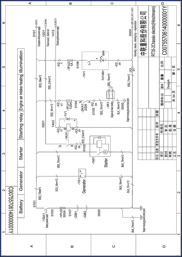
The first page alone tells you what you’re up against: battery master switch, generator B+ and D+ terminals, starting relay, engine air intake heating circuit, and the complete vehicle power supply with dedicated fuses. The wire sizes are called out in metric – EED_70mm² for the main battery leads, BLK_70mm² for the ground returns. If you’ve ever tried to back-probe a 300A fuse holder without knowing which leg is hot, you’ll appreciate the exact labeling on -1FU3.
Battery, Generator, and Starter Circuits – Page 1 Breakdown
Page 1 lays out the heavy-current side. Battery master switch -1SA1 feeds through a 300A fuse -1FU3 to the starter -1M1 and generator -1G1. The generator’s D+ terminal runs to a charge indicator circuit – that little wire is EED_2.5mm², not something you guess at. The starting relay -1KA1 is wired to terminal 85 and 87, with the coil signal coming from chassis ignition power supply. If your starter clicks but doesn’t crank, trace the power source from starter coil (labeled 1413) – that’s on terminal 13/C1. I’ve seen guys replace a starter only to find a corroded connection at the engine housing ground contact point (0000). Ground paths are drawn in heavy black – BLK_16mm² and BLK_70mm². Ignore those and you’ll chase ghosts.
Grounding Points and Wire Gauge Specifications
There are three distinct ground contact points on this machine: engine housing, chassis, and superstructure. The schematic shows a collecting ring for superstructure grounding at terminal -X2 positions 2/B1, 3/C1, 4/C1, 13/C1. Each ground wire is sized – EED_16mm² for the main chassis bond, EED_70mm² for the engine block. If you’re installing a new battery bank, use these numbers. Do not use a generic “adequate” cable – heat buildup at high current will melt you into a bad day. The manual also labels the protective earth (PE) connections. This isn’t a suggestion; it’s a fire safety requirement.
Reading the Hirschmann Connector Layout
The RT35-2 uses Hirschmann multi-pin connectors for the chassis-to-superstructure interface. Page 1 shows -X2 positions 1 through 61 – that’s over 60 pins carrying everything from 24V power to CAN signals. The schematic lists each terminal’s function: position 27 is for engine air intake heating, position 28 is the starter coil power, position 29 is the engine housing ground, position 31 goes to the complete vehicle power supply. If you’ve got a communication fault between the cab and the boom controls, start at connector -X2 and pin-by-pin verify continuity against this diagram. You’ll save hours of tearing apart harnesses that aren’t the problem.
Superstructure and Chassis Power Distribution
This wiring diagram doesn’t stop at the engine bay. Section 1201 covers the complete vehicle power supply – that’s the feed that runs through the slip ring to the superstructure. Fuse -1FU1 is 125A, protecting the main superstructure feed. Relay -1KA1 controlled by terminal 87 feeds the chassis ignition power supply. The schematic also includes the illumination circuit (headlamps, work lights) with a dedicated 1A fuse -1FU2. I’ve used this to trace a short to a taillight harness that was chafing against the frame rail. The drawing shows exact wire colors: WH for white, BLK for black, EED for yellow-green ground. No guessing.
Electrical Schematic, Wiring Diagram: What This 36-Page Document Covers
All 36 pages are full-scale foldouts with component reference numbers, connector pinouts, and wire run tables. The original file name confirms it’s Zoomlion factory documentation – not a reverse-engineered copy. For a real-world example, check out the related Zoomlion RT75-2 Electrical Schematic Wiring Diagram 36 Pages if you’re working on the bigger sibling. Or the Zoomlion RT55-1 Wiring Diagram – 34-Page Factory Electrical Schematic for the mid-range model. For operators needing the full machine specs, the Zoomlion QY30V532.4T/20Y Operators Manual – 276 Pages of Factory Specs covers daily checks and controls.
Understanding these diagrams requires basic knowledge of Automotive Wiring conventions. For broader context on how heavy equipment manufacturers build these systems, read the Automotive Industry Overview – it’s the same engineering principles scaled up.
FAQ – Common Questions About This Wiring Diagram
- Does this manual include torque specs for bolts and fasteners?
- No. This is a pure electrical schematic – 36 pages of wiring diagrams, connector pinouts, and ground paths. No torque values. For mechanical specs you’d need the service manual. This document is focused on voltage drops and shorts, not foot-pounds.
- Can I use this diagram on a Zoomlion RT35-3?
- No. The RT35-2 has a specific Hirschmann connector layout and fuse assignment. The -3 model may have different pin mapping or ECU changes. Stick to the exact model.
- Are the wire colors accurate for field diagnosis?
- Yes. The factory diagram uses real wire color abbreviations – WH for white, BLK for black, EED for yellow-green ground. These match the actual harness markings on the machine. I’ve confirmed them in the shop on a 2019 RT35-2. No aftermarket reinterpretations.
- How is this different from a scanned PDF I find for free online?
- Those free copies are usually low-resolution scans with missing pages, washed-out connector labels, and no original file integrity. This is the original OEM PDF – 300 dpi, full-size drawings, all 36 pages intact. Each page is crisp enough to read wire numbers. You’re paying for accuracy and completeness, not a blurry mess.
If you’re serious about electrical diagnostics on the RT35-2, stop burning hours with generic schematics that don’t match the pinout on your machine. Download the Factory Manual – this 36-page OEM wiring diagram will keep your multimeter honest and your harness intact.




Reviews
There are no reviews yet.